Format: PDF
Pages: 3,100+
Compatible with: Windows/Mac/Tablet
File size: 230mb
Includes CHASSIS WORKSHOP MANUAL 00ELT0104, ENGINE WORKSHOP MANUAL 00ELT0103 AND ELECTRICAL WORKSHOP MANUAL 00ELT0105
Covers: Mitsubishi FUSO Canter Euro6 FE, FG Truck (Europe) Service & Repair
- FE and FG series
- Mits/Iveco 4P10-T2, 4P10-T4 or 4P10-T6 engine
- Euro 6 OBD only
- See full model list at bottom of page
Chassis Workshop Manual Topics:
GENERAL INFORMATION
SPECIFICATIONS
MAINTENANCE
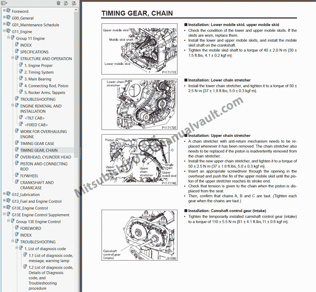
ENGINE
LUBRICATION
FUEL AND ENGINE CONTROL
COMMON RAIL SYSTEM
COOLING
INTAKE AND EXAUST
EMISSION CONTROL
BlueTec SYSTEM
GROUP INDEX
CLUTCH
GEARBOX <M038: DUONIC>
GEARBOX <M038>
REAR SUSPENSION
HANDBRAKE
STEERING <RIGID LEAF SUSPENSION>
ABS/ESP/ASR
BRAKE
PROPELLER SHAFT
FRONT AXLE <RIGID LEAF SUSPENSION (FE)>
REAR AXLE
WHEEL, TYRE
FRONT SUSPENSION <RIGID LEAF TYPE>
TRANSFER
FRONT AXLE <RIGID LEAF SUSPENSION (FG)>
FRONT AXLE <INDEPENDENT SUSPENSION>
FRONT SUSPENSION <INDEPENDENT TYPE>
STEERING <INDEPENDENT SUSPENSION>
ENGINE STARTING, STOPPING AND PREHEATING CIRCUIT
LIGHTING CIRCUIT
METER CIRCUIT
INDICATOR AND WARNING LIGHT CIRCUIT
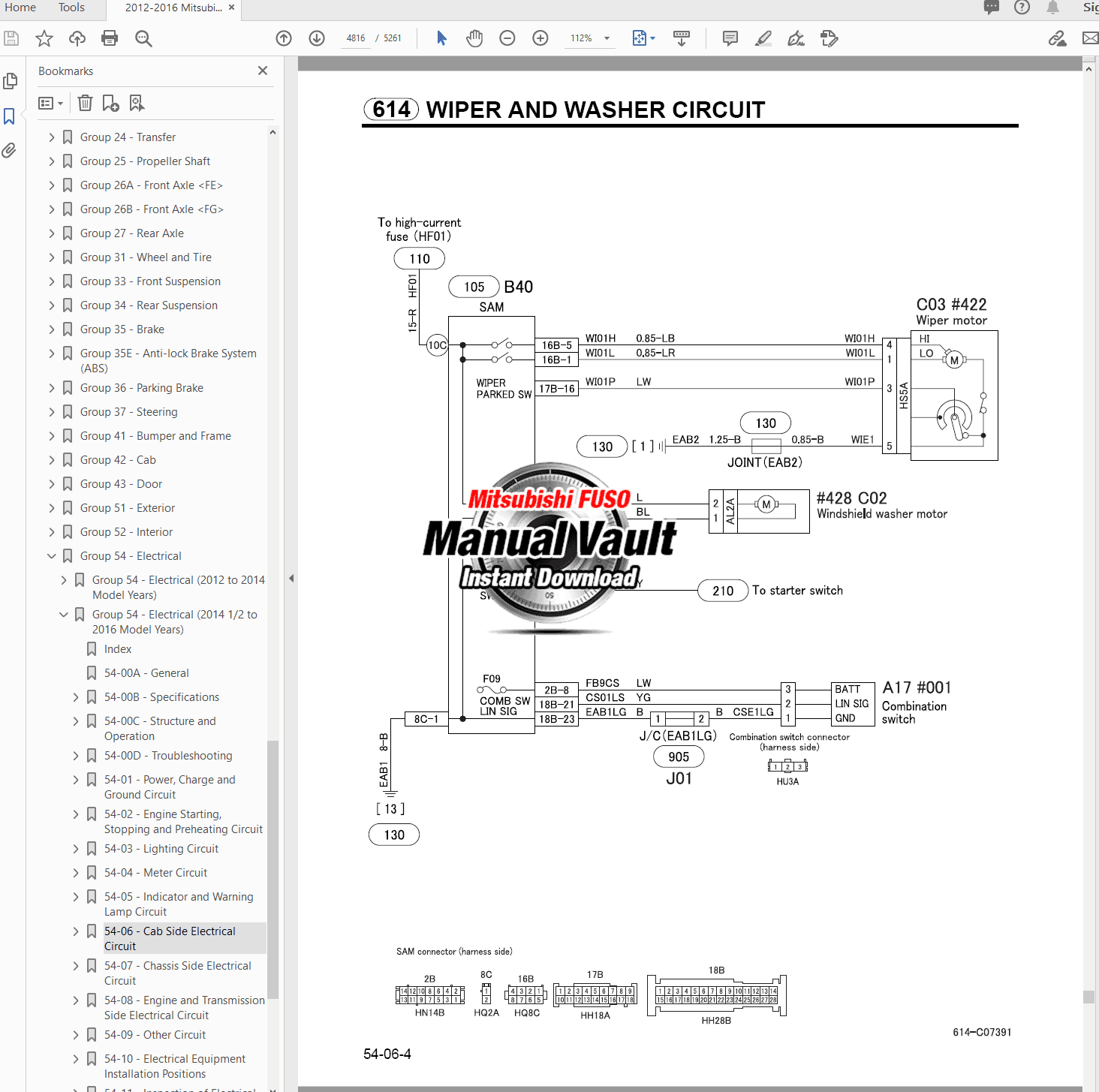
CAB SIDE ELECTRICAL CIRCUIT
BUMPER, FRAME
CAB MOUNTING, TILT
DOOR
EXTERIOR
INTERIOR
Electrical Workshop Manual Topics:
GENERAL
SPECIFICATIONS
STRUCTURE AND OPERATION
TROUBLESHOOTING
POWER, CHARGE AND EARTH CIRCUIT
ENGINE STARTING, STOPPING AND PREHEATING CIRCUIT
LIGHTING CIRCUIT
METER CIRCUIT
INDICATOR AND WARNING LAMP CIRCUIT
CAB SIDE ELECTRICAL CIRCUIT
CHASSIS SIDE ELECTRICAL CIRCUIT
ENGINE AND GEARBOX SIDE ELECTRICAL CIRCUIT
OTHER CIRCUIT
ELECTRICAL EQUIPMENT INSTALLATION POSITIONS
INSPECTION OF ELECTRICAL EQUIPMENT
STARTER AND ALTERNATOR
ON-VEHICLE INSPECTION AND ADJUSTMENT
CONNECTOR CONFIGURATION CHART
IDLING STOP AND START SYSTEM
LDWS (LANE DEPARTURE WARNING SYSTEM)
IMMOBILISER
METER CLUSTER
SIGNAL DETECTED AND ACTUATION MODULES
Engine Workshop Manual Topics:
GENERAL INFORMATION
4P10T2, 4P10T4, 4P10T6 ENGINE (SPECIFICATIONS, SERVICE, ETC)
LUBRICATION
FUEL AND ENGINE CONTROL
COMMON RAIL SYSTEM
COOLING SYSTEM
INTAKE AND EXHAUST
EMISSION CONTROL
BlueTec SYSTEM
Full Model List:
- FEA01BL4SEU2
- FEA01BL4SEU3
- FEA01CL4SEU2
- FEA01CL4SEU3
- FEA51BL4SEU3
- FEA51CL4SEU3
- FEA51EL4SEU3
- FEB01BL4SEU2
- FEB01BL4SEU3
- FEB01CL4SEU2
- FEB01CL4SEU3
- FEB01EL4SEU2
- FEB01EL4SEU3
- FEB01EL4WEU2
- FEB01GL4SEU2
- FEB01GL4SEU3
- FEB71CL4SEU3
- FEB71CL4SEU4
- FEB71EL4SEU3
- FEB71EL4SEU4
- FEB71GL4SEU3
- FEB71GL4SEU4
- FEB71GL4WEU3
- FEB71GL4WEU4
- FEC71HL4SEU3
- FEC71HL4SEU4
- FEC71KL4SEU4
- FEB01BR4SEU2
- FEB01CR4SEU2
- FEB01ER4SEU2
- FEB01ER4WEU2
- FEB01GR4SEU2
- FEB71CR4SEU3
- FEB71ER4SEU3
- FEB71GR4SEU3
- FEB71GR4WEU3
- FEC71HR4SEU3
- FEC71KR4SEU3
- FEA01BL3SEU2
- FEA01BL3SEU3
- FEA01CL3SEU2
- FEA01CL3SEU3
- FEB01BL3SEU2
- FEB01BL3SEU3
- FEB01CL3SEU2
- FEB01CL3SEU3
- FEB01EL3SEU2
- FEB01EL3SEU3
- FEB01EL3WEU3
- FEB01GL3SEU2
- FEB01GL3SEU3
- FEB71CL3SEU3
- FEB71EL3SEU3
- FEB71EL3SEU4
- FEB71GL3SEU3
- FEB71GL3SEU4
- FEB71GL3WEU4
- FECX1EL3SEU4
- FECX1GL3SEU4
- FECX1HL3SEU4
- FECX1KL3SEU4
- FEC71HL3SEU3
- FEC71HL3SEU4
- FEC71KL3SEU4
- FEC71KL3WEU4
- FEB01BR3SEU2
- FEB01BR3SEU3
- FEB01CR3SEU2
- FEB01CR3SEU3
- FEB01ER3SEU2
- FEB01ER3SEU3
- FEB01ER3WEU3
- FEB01GR3SEU2
- FEB01GR3SEU3
- FEB71CR3SEU3
- FEB71ER3SEU3
- FEB71ER3SEU4
- FEB71GR3SEU3
- FEB71GR3SEU4
- FECX1ER3SEU4
- FECX1GR3SEU4
- FECX1HR3SEU4
- FECX1KR3SEU4
- FEC71HR3SEU3
- FEC71HR3SEU4
- FEC71KR3SEU3
- FEC71KR3SEU4
- FEC71KR3WEU4
- FGB71EL6SEU4
- FGB71EL6WEU4
- FGB71GL6SEU4
- FGB71GL6WEU4
- FGB71ER6SEU4
- FGB71ER6WEU4
- FGB71GR6SEU4