Format: PDF
Pages: 1,734
Compatible with: Windows/Mac/Tablet/Phone
Covers: 1990-1991 Mitsubishi FUSO FE, FG Series Truck (US/Canada) Service & Repair
Manual Part Number: TWSE8911
Topics List:
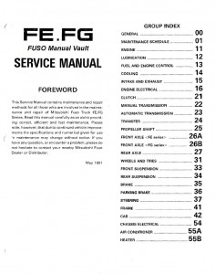
Foreword
1. Group Classification
2. Definition of Terms and Unit Used
3. Notes On Illustrations
Group 00 – General
1. Exterior Views
2. Major Specifications
3. Power Train Table
4. Equipment Model Notation
5. Performance Curves
5.1 Operation Performance Curves
5.2 Engine Performance Curves
6. Servicing Precautions
7. Vehicle Identification Number
8. Standard Bolts and Nuts Tightening Torque Table
Group 01 – Maintenance Schedule
1. Using the Maintenance Schedule Table
2. Maintenance Schedule Table
2.1 Replacement of Oil Filter Element
2.2 Replacement of the Fuel Filter Element
2.3 Cleaning of the Fuel Feed Pump Gauze Filter
2.4 Bleeding of the Fuel System
2.5 Adjustment of V-Belt Tension
2.6 Cleaning and Replacement of Air Cleaner Element
2.6.1 Dry Dust Buildup
2.6.2 Oil Smoke, Soot, and Oil Black Deposits
2.6.3 Inspection After Drying
2.7 Inspection of Clutch Pedal
2.7.1 Inspection of Pedal Play
2.7.2 Clearance to Floorboard When Released
2.7.3 Clutch Operation
2.8 Servicing of Tires
2.8.1 Tire Inflation Pressure
2.8.2 Removal of Tire
2.8.3 Installation of Tire
2.8.4 Retightening of Wheel Nuts
2.8.5 Tire Rotation
2.9 Servicing of Air Drier
2.10 Adjustment of Wheel Brake Shoe Clearance
2.10.1 Adjusting Gear Type [FK415, FK455]
2.10.2 Adjusting Cam Type [FM555]
2.11 Adjustment of Parking Brake Shoe Clearance
2.12 Servicing of Battery
2.12.1 Cleaning of Battery Terminals
2.12.2 Inspection of Fluid Level
2.12.3 Specific Gravity
2.13 Replacement of Fuses
3. Lubrication
3.1 Engine
3.1.1 Engine Oil Level and Contamination
3.1.2 Replacement of Engine Oil
3.2 Clutch
3.2.1 Inspection of Fluid Level of the Clutch Reservoir Tank
3.2.2 Replacement of Brake Fluid
3.2.3 Bleeding of Clutch System
3.3 Transmission
3.3.1 Inspection of Transmission Gear Oil Level
3.3.2 Replacement of Transmission Gear Oil
3.4 Rear Axle
3.4.1 Inspection of Rear Axle Gear Oil Level
3.4.2 Replacement of Rear Axle Gear Oil
3.5 Brakes
3.5.1 Inspection of Fluid Level of the Brake Reservoir Tank
3.5.2 Replacement of Brake Fluid
3.5.3 Bleeding of the Brake System
3.6 Power Steering
3.6.1 Inspection of Power Steering Oil Level
3.6.2 Replacement of Power Steering Oil
3.6.3 Bleeding of the Power Steering System
3.7 Lubrication
Group 11 – Engine
1. General
1.1 Engine Proper
1.2 Air Compressor
2. Specifications
3. Service Standards
3.1 Service Standard Table
3.2 Tightening Torque Table
3.3 Sealant, Oil and Grease
4. Service Procedure
4.1 Engine Proper
4.1.1 Measurement of Compression Pressure
4.1.2 Removal
4.1.3 Disassembly
4.1.4 Inspection and Correction
4.1.5 Reassembly
4.1.6 Installation
4.1.7 Adjustment
4.2 Air Compressor
4.2.1 Removal
4.2.2 Disassembly
4.2.3 Inspection and Correction
4.2.4 Reassembly
4.2.5 Installation
5. Special Tool
6. Troubleshooting
6.1 Engine
6.2 Valve Mechanism
Group 12 – Lubrication
1. General
2. Specifications
3. Service Standards
3.1 Service Standard Table
3.2 Tightening Torque Table
4. Service Procedure
4.1 Oil Pump
4.1.1 Removal
4.1.2 Disassembly and Inspection
4.1.3 Reassembly
4.1.4 Installation
4.2 Oil Filter, Oil Cooler
4.2.1 Disassembly and Inspection
4.3 Regulator Valve, Check Valve [6D14T]
4.3.1 Regulator Valve
4.3.2 Check Valve [6D14T]
5. Special Tool
6. Troubleshooting
Group 13 – Fuel
1. General
1.1 Fuel System
1.2 Engine Control
2. Specifications
3. Service Standards
3.1 Service Standard Table
3.2 Tightening Torque Table
4. Service Procedure
4.1 Injection Pump
4.1.1 Removal
4.1.2 Disassembly
4.1.3 Inspection and Correction
4.1.4 Reassembly
4.1.5 Test and Adjustment
4.2 Governor
4.2.1 Removal and Disassembly
4.2.2 Inspection and Reassembly
4.2.3 Adjustment
4.3 Auto Timer
4.3.1 Disassembly and Inspection
4.3.2 Reassembly
4.3.3 Adjustment
4.4 Feed Pump
4.4.1 Disassembly and Reassembly
4.4.2 Test
4.5 Injection Nozzle
4.5.1 Removal
4.5.2 Disassembly
4.5.3 Cleaning and Inspection
4.5.4 Reassembly
4.5.5 Test and Adjustment
4.5.6 Installation
4.6 Fuel Filter
4.6.1 Disassembly and Reassembly
4.7 Water Separator
4.7.1 Disassembly and Reassembly
4.8 Bleeding the Fuel System
4.9 Engine Control
4.9.1 Removal and Installation
4.9.2 Adjustment
5. Special Tool
6. Troubleshooting
Group 14 – Cooling
1. General
2. Specifications
3. Service Standards
3.1 Service Standard Table
3.2 Tightening Torque Table
3.3 Sealant, Oil and Grease
4. Service Procedure
4.1 Auto Cool Fan Coupling
4.1.1 Removal and Disassembly
4.1.2 Inspection and Correction
4.1.3 Reassembly and Installation
4.2 Water Pump
4.2.1 Removal
4.2.2 Disassembly and Inspection
4.2.3 Reassembly
4.3 Thermostat
4.3.1 Removal and Disassembly
4.3.2 Inspection
4.4 Radiator
4.4.1 Removal and Disassembly
4.4.2 Inspection
4.4.3 Installation
4.4.4 Gas Leak Test
4.5 Reservoir Tank
4.5.1 Removal and Inspection
4.6 Cleaning of Cooling System
5. Special Tool
6. Troubleshooting
Group 15 – Intake and Exhaust
1. General
2. Specifications
3. Service Standards
3.1 Service Standard Table
3.2 Tightening Torque Table
4. Service Procedure
4.1 Turbocharger [6D14T]
4.1.1 Removal
4.1.2 Disassembly
4.1.3 Inspection and Correction
4.1.4 Reassembly
4.1.5 Installation
4.1.6 Adjustment
4.2 Air Cleaner
4.2.1 Disassembly and Reassembly
4.2.2 Inspection and Cleaning
4.3 Inlet Manifold
4.4 Exhaust Manifold
4.5 P.C.V. (Positive Crankcase Ventilation) Valve [6D14T]
5. Special Tool
6. Troubleshooting
Group 16 – Engine Electrical
1. General
2. Specifications
3. Service Standards
3.1 Service Standard Table
3.2 Tightening Torque Table
3.3 Sealant, Oil and Grease
4. Service Procedure
4.1 Starter
4.1.1 Removal
4.1.2 Disassembly
4.1.3 Inspection
4.1.4 Reassembly
4.2 Alternator
4.2.1 Removal
4.2.2 Disassembly
4.2.3 Inspection
4.2.4 Reassembly
4.2.5 Tests
4.2.6 Installation
4.3 Glow Plug System
4.3.1 Removal and Installation
4.3.2 Inspection
5. Troubleshooting
Group 21 – Clutch [C5W33]
1. General
1.1 Clutch Control
1.2 Clutch Proper
2. Specifications
3. Service Standards
3.1 Service Standard Table
3.2 Tightening Torque Table
4. Service Procedure
4.1 Removal
4.1.1 Removal From Vehicle
4.2 Clutch Proper
4.2.1 Disassembly and Inspection
4.2.2 Reassembly and Adjustment
4.3 Clutch Pedal
4.3.1 Diassembly and Inspection
4.3.2 Reassembly and Adjustment
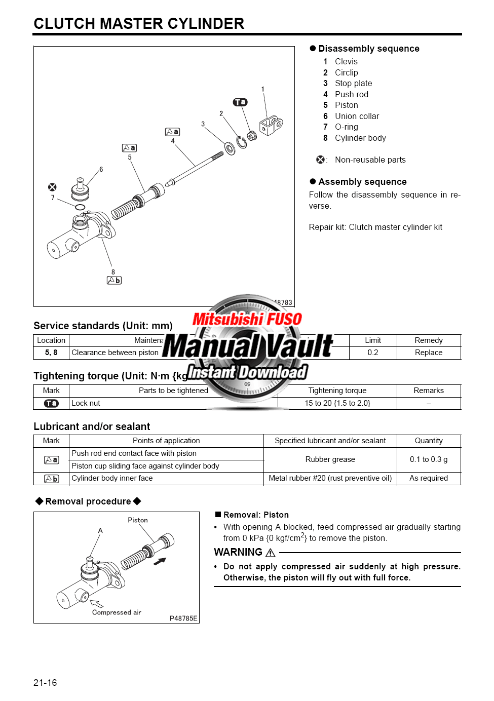
4.4 Clutch Master Cylinder
4.4.1 Disassembly and Inspection
4.4.2 Reassembly and Adjustment
4.5 Clutch Power Cylinder
4.5.1 Disassembly and Inspection
4.5.2 Reassembly
4.6 Replacement of Clutch System Fluid
4.7 Bleeding Clutch System
4.8 Adjustment of Clutch Control
5. Special Tool
6. Troubleshooting
Group 21 – Clutch [C6W35]
1. General
1.1 Clutch Control
1.2 Clutch Proper
2. Specifications
3. Service Standards
3.1 Service Standard Table
3.2 Tightening Torque Table
4. Service Procedure
4.1 Removal
4.1.1 Removal from Vehicle
4.2 Clutch Proper
4.2.1 Disassembly and Inspection
4.2.2 Reassembly and Adjustment
4.3 Clutch Pedal
4.3.1 Disassembly and Inspection
4.3.2 Reassembly and Adjustment
4.4 Clutch Master Cylinder
4.4.1 Disassembly and Inspection
4.4.2 Reassembly and Adjustment
4.5 Clutch Booster
4.5.1 Disassembly and Inspection
4.5.2 Reassembly and Adjustment
4.6 Inspection of Clutch Disc Wear
4.7 Replacement of Clutch System Fluid
4.8 Bleeding Clutch System
4.9 Adjustment of Clutch Control
5. Special Tool
6. Troubleshooting
Group 22 – Transmission [M5S5]
1. General
2. Specifications
3. Service Standards
3.1 Service Standard Table
3.2 Tightening Torque Table
4. Service Procedure
4.1 Key Points for Removal
4.2 Key Points for Installation
4.3 Adjustment After Installation
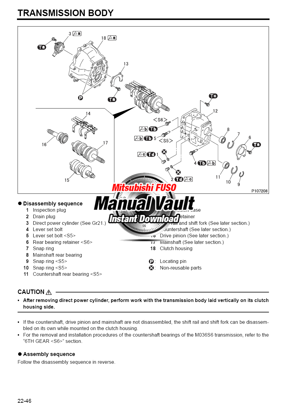
4.4 Disassembly, Inspection and Reassembly
4.4.1 Transmission Assembly
4.4.2 Main Shaft
4.4.3 Counter Shaft Gear
4.4.4 Reverse Gear
4.4.5 Drive Pinion
4.4.6 Reassembly of Clutch Housing
4.4.7 Gearshifter, Lower
4.4.8 Gearshifter, Upper
4.4.9 Rear Cover
4.4.10 Speedometer Gears
4.4.11 Transmission Control
5. Special Tool
6. Troubleshooting
Group 22 – Transmission [M6S5]
1. General
2. Specifications
3. Service Standards
3.1 Service Standard Table
3.2 Tightening Torque Table
4. Service Procedure
4.1 Key Points for Removal
4.2 Key Points for Installation
4.3 Adjustment After Installation
4.4 Disassembly, Inspection and Reassembly
4.4.1 Transmission Assembly
4.4.2 Main Shaft
4.4.3 Counter Shaft Gear
4.4.4 Reverse Gear
4.4.5 Drive Pinion
4.4.6 Reassembly of Clutch Housing
4.4.7 Gearshifter, Lower
4.4.8 Gearshifter, Upper
4.4.9 Rear Cover
4.4.10 Speedometer Gears
4.4.11 Transmission Control
5. Special Tool
6. Troubleshooting
Group 22 – Transmission [M8S2x5]
1. General
2. Specifications
2.1 Transmission Proper
2.2 Transmission Control
3. Service Standards
3.1 Service Standard Table
3.2 Tightening Torque Table
4. Service Procedure
4.1 Key Points for Removal
4.2 Key Points for Installation
4.3 Adjustment After Installation
4.4 Disassembly, Inspection and Reassembly
4.4.1 Transmission Assembly
4.4.2 Main Shaft
4.4.3 Counter Shaft Gear
4.4.4 Reverse Gear
4.4.5 Drive Pinion
4.4.6 Reassembly of Clutch Housing
4.4.7 Gearshifter, Lower
4.4.8 Gearshifter, Upper
4.4.9 Splitter, Upper
4.4.10 Rear Cover
4.4.11 Speedometer Gears
4.4.12 Splitter Case and Gears
4.4.13 Power Shift
4.4.14 Splitter Control
4.4.15 Transmission Control
5. Special Tool
6. Troubleshooting
Group 25 – Propeller Shaft
1. General
2. Specifications
3. Service Standards
3.1 Service Standard Table
3.2 Tightening Torque Table
4. Service Procedure
4.1 Removal and Installation
4.2 Disassembly, Inspection and Correction
4.3 Reassembly
4.4 Propeller Shaft Dynamic Balance Adjustment Procedures
5. Special Tool
6. Troubleshooting
Group 26 – Front Axle
1. General
2. Specifications
3. Service Standards
3.1 Service Standard Table
3.2 Tightening Torque Table
4. Service Procedure
4.1 Removal and Installation
4.2 Wheel Hub and Brake Drum
4.2.1 Disassembly, Inspection and Correction
4.2.2 Reassembly
4.2.3 Adjustment of Bearing Starting Torque
4.3 Front Axle, Knuckle and Kingpin
4.3.1 Disassembly, Inspection and Correction
4.3.2 Measurement of Front Axle Bends
4.3.3 Measurement of Kingpin Inclination
4.3.4 Reassembly
4.4 Adjustment After Installation (Wheel Alignment)
5. Special Tool
6. Troubleshooting
Group 27 – Rear Axle
1. General
2. Specifications
3. Service Standards
3.1 Service Standard Table
3.2 Tightening Torque Table
4. Service Procedure
4.1 Removal and Installation
4.2 Wheel Hub and Brake Drum
4.2.1 Disassembly, Inspection and Correction
4.2.2 Reassembly
4.2.3 Adjustment of Bearing Starting Torque
4.3 Reduction and Differential
4.3.1 Disassembly, Inspection and Correction
4.3.2 Reassembly
4.3.3 Adjustment of Starting Torque of Reduction Pinion Bearing
4.3.4 Selection of Reduction Pinion Mounting Adjusting Shim
4.3.5 Adjustment of Differential Case Side Bearing and Reduction Gear
4.3.6 Reduction Gear Tooth Contact
5. Special Tool
6. Troubleshooting
Group 31 – Wheel and Tire
1. Specifications
2. Service Procedure
3. Service Standards
3.1 Service Standard Table
3.2 Tightening Torque Table
4. Troubleshooting
Group 33 – Front Suspension
1. General
2. Specifications
3. Service Standards
3.1 Service Standard Table
3.2 Tightening Torque Table
4. Service Procedure
4.1 Removal and Installation
4.2 Disassembly, Inspection and Correction
4.3 Reassembly
5. Special Tool
6. Troubleshooting
Group 34 – Rear Suspension
1. General
2. Specifications
3. Service Standards
3.1 Service Standard Table
3.2 Tightening Torque Table
4. Service Procedure
4.1 Removal and Installation
4.2 Disassembly, Inspection and Correction
4.3 Reassembly
5. Special Tool
6. Troubleshooting
Group 35 – Brake
1. General
1.1 Service Brake
1.2 Parking Brake
1.3 Exhaust Brake
2. Specifications
2.1 Service Brake
2.2 Parking Brake
2.3 Exhaust Brake
3. Service Standards
3.1 Service Standard Table
3.1.1 Service Brake
3.1.2 Parking Brake
3.1.3 Exhaust Brake
3.2 Tightening Torque Table
3.2.1 Service Brake
3.2.2 Parking Brake
3.2.3 Exhaust Brake
4. Service Procedure of Service Brake
4.1 Brake System Diagram
4.2 Brake Pedal and Air Brake Valve
4.2.1 Removal and Installation
4.2.2 Brake Pedal
4.2.3 Air Brake Valve
4.2.4 Inspection and Adjustment After Reassembly
4.3 Brake Booster
4.3.1 Brake Booster for FK Series
4.3.2 Brake Booster for FM Series
4.3.3 Function Check After Reassembly
4.4 Air Pressure Governor
4.4.1 Function Check
4.4.2 Disassembly, Inspection and Correction
4.4.3 Reassembly
4.4.4 Inspection and Adjustment After Reassembly
4.5 Check Valve
4.5.1 Disassembly, Inspection and Correction
4.5.2 Reassembly and Inspection
4.6 Safety Valve
4.7 Low Air Pressure Switch
4.8 Stop Lamp Switch
4.9 Supply Valve
4.9.1 Disassembly, Inspection and Correction
4.9.2 Reassembly and Adjustment
4.10 Air Drier
4.10.1 Maintenance and Inspection
4.10.2 Disassembly, Inspection and Correction
4.10.3 Reassembly
4.10.4 Inspection After Installation in Vehicle
4.10.5 Troubleshooting
4.11 Wheel Brake
4.11.1 Removal and Installation
4.11.2 Disassembly, Inspection and Correction
4.11.3 Reassembly
4.11.4 Replacement of Brake Lining and Correction of Brake Drum
4.12 Inspection and Adjustment After Installation
4.12.1 Replacement of Brake Fluid and Bleeding of Brake (Oil) System
4.12.2 Brake Shoe Clearance Adjustment
5. Service Procedure of Parking Brake
5.1 Parking Brake Drum Assembly
5.1.1 Key Points for Removal
5.2 Parking Brake Proper
5.3 Parking Brake Control
5.4 Adjustment After Installation
6. Service Procedure of Exhaust Brake
6.1 Exhaust Brake Valve
6.1.1 Disassembly and Inspection
6.1.2 Reassembly and Adjustment
6.2 Control Cylinder
6.2.1 Disassembly and Inspection
6.2.2 Reassembly
6.3 Exhaust Brake Microswitch
7. Special Tool
7.1 Service Brake
7.2 Parking Brake
8. Troubleshooting
Group 37 – Steering
1. General
2. Specifications
3. Service Standards
3.1 Service Standard Table
3.2 Tightening Torque Table
4. Service Procedure
4.1 Removal and Installation of Steering System
4.1.1 Removal of Starter Switch Wires and Cables
4.1.2 Removal of Upper and Lower Shaft Assembly
4.1.3 Removal of Starter Switch
4.1.4 Installation of Starter Switch
4.2 Disassembly and Reassembly of Steering Wheel
4.3 Steering Shaft
4.3.1 Disassembly, Inspection and Correction
4.3.2 Reassembly
4.4 Details of Link and Bracket Section
4.5 Drag Link
4.6 Tie Rod
4.7 Integral Power Steering Booster
4.7.1 Disassembly, Inspection and Correction
4.7.2 Reassembly and Adjustment
4.8 Power Steering Oil Pump
4.8.1 Disassembly, Inspection and Correction
4.8.2 Reassembly
4.8.3 Adjustment
4.9 Power Steering Oil Tank
4.9.1 Disassembly
4.9.2 Reassembly
4.10 Adjustment After Installation
4.10.1 Bleeding
4.10.2 Performance Verification Tests
4.10.3 Steering Wheel Play
4.10.4 Adjustment of Steering Angle
5. Special Tool
6. Troubleshooting
Group 41 – Frame
1. General
2. Specifications
3. Service Procedure
3.1 Frame
3.2 Rivets
3.3 Shape of Frame
4. Troubleshooting
Group 42 – Cab
1. General
2. Specifications
3. Service Standards
3.1 Tightening Torque Table
4. Service Procedure
4.1 Key Points for Cab Removal and Installation
4.1.1 Removal
4.1.2 Installation
4.2 Doors
4.2.1 Removal of Doors
4.2.2 Door Installation Adjustment
4.2.3 Door Trim
4.2.4 Door Locking System
4.2.5 Parts Related to Glass
4.3 Seats
4.3.1 Seats
4.3.2 Seat Belts
4.4 Floor Mat
4.5 Overhead Console
4.6 Trims
4.7 Instrument Panel
4.8 Windshield Glass and Rear Window Glass
4.8.1 Removal
4.8.2 Installation
4.9 Rearview Mirrors
4.10 Removal of Front Panel and Related Parts
5. Troubleshooting
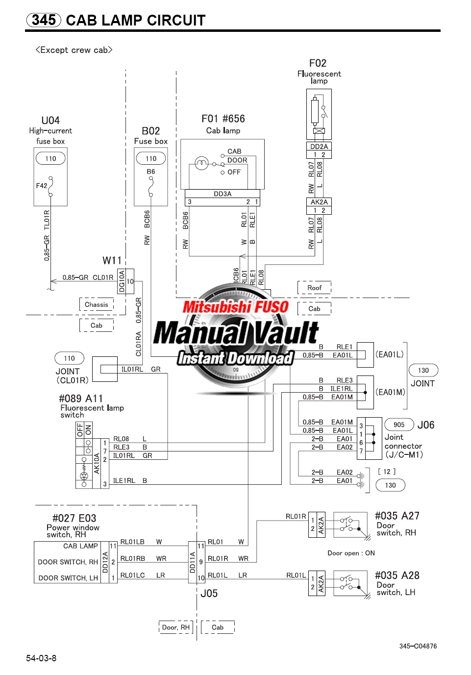
Group 54 – Chassis Electrical
1. General
2. Specifications
2.1 Electrical
2.2 Meter and Gauge
2.3 Lighting
2.4 Exhaust Brake
2.5 Wiper and Washer
2.6 Accessory
3. Service Procedure
3.1 Aiming of Headlamps
3.2 Warning and Indicator Lamps
4. Troubleshooting
Group 55 – Heater
1. General
2. Specifications
3. Service Procedure
3.1 Removal and Installation
3.2 Cleaning of Air Filter
3.3 Heater Control Adjustment Procedures
4. Troubleshooting
Wiring Diagram
Alphabetical Index